Once again, we visit the topic of couplers. Some time ago, we talked about different options for model couplers. Specifically, we talked about what is available HO gauge model trains. Today, we are going to talk about what the prototypes, and how they are used. I will warn you, this is a pretty technical post.
The modern knuckle coupler came to be in 1873. Eli H. Janney is credited with the invention of the knuckle coupler, and his design is considered to be one of the most important advances in railroad technology, along with the Westinghouse Air Brake. Both of those inventions completely changed how railroads operated, and made them significantly safer.
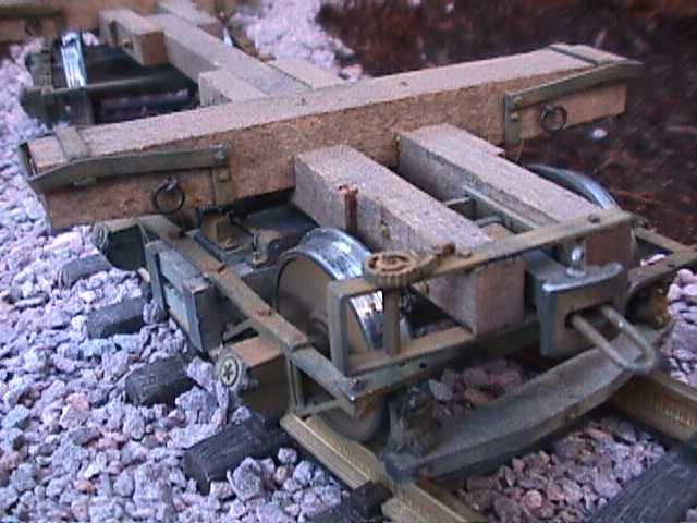 |
Photo from the Santa Cruz Lumber
Company Garden Railway.
www.santacruzlumberco.com |
Before the invention of the modern knuckle coupler, railroads used a system of links and pins to connect railroad cars and locomotives. The design was simple, but very dangerous. It consisted of a socket on the ends of each car, and a link, similar to the link of a chain, being placed in the sockets. Pins dropped through the sockets, and through an end of the link, to connect the cars. A photo of this is on the right. That link, sticking out of the socket, fits into a similar socket on another car. A pin on each car secures everything in place. There were three primary reasons this system was so dangerous. First of all, it required the brakeman to stand between two cars as they were being coupled. If they were coupled hard, that could mean the brakeman got run over. Also, it meant that the brakeman had to align the pin with the opposing socket. Again, a hard coupling could mean injury. Many brakemen lost fingers and hands during coupling operations. Many brakemen were killed just trying to couple cars. The third problem was that there was often quite a lot of slack in a coupling. This meant cars could move several inches, or even up to a foot without disturbing the other car. When the train began to move, all the slack was pulled out, however, as a train slowed down, the slack all ran in. If heavier cars were behind lighter cars, and all that slack ran into the lighter cars, it could mean a derailment. Because of these safety problems, link and pin couplers are banned from interchange service in the U.S. That is to say, they cannot be used on railroad cars that will leave home rails.
In April 1873, Eli Janney filed for a patent for his knuckle couplers. Since then, many variations have been produced, however the principle has remained the same. The knuckle opens by pulling up on a link on the top of the coupler. Often these links are connected to bars, allowing this operation to be done from the side of the train. The link releases a pin inside the unit, which allows the knuckle to swing freely. The knuckle is connected to a tongue inside the coupler. As two couplers meet, the knuckles push on the opposing tongues, forcing the couplers closed. Gravity drops the pin back in place, locking the couplers. (See the animation below.) Because of the automatic nature of the couplers, there is no need for a person to stand between cars or have their fingers near the couplers. Despite the obvious safety reasons, this type of coupler was not required by law until 1893, and it was not standardized until 1916. For those of you who learn better by seeing, take a look at the animation below. It shows the basics of coupler operation. The green parts represent the knuckle. The white circle is where the pin drops to lock the couplers. This would be a view looking down, at the top of the couplers.
 |
| Knuckle couplers in operation. Animation from www.railway-technical.com. |
 |
Type E coupler.
Photo from Wikipedia. |
The most basic of the "Janney" coupler is called the type E. The type E coupler, on the right, is also the most common. This design can be found on almost any type of freight cars or locomotives anywhere in North America. This specific variation of Janney's coupler was designed in 1932, and has been in widespread use since then. Variations have developed since then for added safety, and for use in special circumstances.
 |
The left coupler has a lower shelf.
Photo from forum.atlassrr.com. |
One of the variations designed for the type E coupler was to solve the problem of the coupler being able to uncouple if an extreme vertical force was placed on one or both coupled cars. By the nature of the coupler, it is possible for couplers to slide up or down, and an extreme movement up or down would result in the couplers sliding apart, without the opening of the knuckles. To solve this potential, although rare problem, shelves were added to the design. There are two variations of shelves. Some have just a lower shelf, as seen on the left, and others have a double shelf. Lower shelf type E coupler can be found on just about any type of freight car. They are typically found on cars that are less than about 30 years old, as the couplers came into use in the late 1970's.
 |
Type E Double Shelf Coupler
Photo from www.model-railroad-hobbyist.com |
The double shelf couplers have a shelf both above and below the knuckle, or coupling face of the coupler. Again, this is to prevent couplers from sliding apart. Double shelf couplers are required in the United States on all tank cars carrying hazardous materials. This prevents couplers from coming apart in a derailment and puncturing the tank car. The photo on the right is an example of a double shelf coupler. This is a model, of such a coupler, but it accurately represents a modern type E double shelf coupler.
These type E couplers eliminated the biggest safety problems for brakemen. It keeps them and their hands away from the couplers during operations. It also keeps them out of the way of moving railroad equipment. It partially solved the problem of the slack between cars, but did not eliminate it. The slack was reduced enough to make it acceptable for freight trains, but it still allowed for some pretty uncomfortable jerking and bouncing in passenger operations. Even in freight operations, it would be ideal to have no slack between cars. Developments in couplers continued to try to eliminate slack from couplings. The first of this development was the type F coupler.
 |
Type F coupler
Image from www.mcconway.com |
The type F coupler, seen on the left, was developed with shelves, and also with a type of tooth and socket. The tooth and socket system was fitted to the sides of the design, and was supposed to help eliminate slack as much as possible between cars. Versions were designed with just a lower shelf, and also with a double shelf, just as with the type E coupler. The most common just has the lower shelf, as seen on the left. The reasoning on the lower shelf here really had nothing to do with the couplers sliding apart. The tooth and socket system prevents that. However, these couplers are massive. It was thought that if one was to break and fall into the track area, it could potentially derail the train behind it. The lower shelf was built into the design to basically hold onto the opposing coupler, in the event of a break, and prevent it from falling into the tracks. The type F coupler is found on a many modern locomotives. It is also found on a lot of the rotary dump coal cars, because it prevents the cars from coming uncoupled while being dumped.
 |
Type H coupler.
Photo by James Ogden |
The type H coupler, on the right, is very similar to the type F coupler, and its main function is to eliminate slack between couplers. This is known as a tightlock coupler, because there is no slack in the coupling. Type H couplers have a similar appearance to the type F couplers. They have the tooth and socket system on the sides, however, there are no shelves on a type H. These couplers are found almost exclusively on passenger trains. Occasionally they are found on locomotives dedicated to passenger service, although more often those use type F couplers. There are two reasons these are used exclusively on passenger trains. First, they eliminate coupler slack, which makes for a much more comfortable ride. Secondly, in a derailment, a type H coupler generally stays coupled, eliminating the possibility of having the passenger cars jackknife. In derailments where passenger cars jackknife, the number of serious injuries is typically significantly higher. These couplers usually prevent that from happening.
Couplers have come a long way since the days of the link and pin. They have also come a long was since Eli H. Janney first patented his new, safe, automatic knuckle coupler. Safety has improved greatly, and continues to do so with the variations on Janney's coupler. The basic design has remained the same since 1873, but the details have changed and standardized in the years since. The type E, F, and H couplers are the industry standard today, and have proven to be reliable and safe. When you are out railfanning, take a closer look at the couplers. That is the best way to figure out what to put on your models. You will start to see how different couplers are used, and see them in operation.


2 comments:
Thanks, just what I was looking for! Very well explained it so I could visualise and understand.
Janney invented it and you have shown us how it works
More info on couplers at
obts.fandom.com/RailCar_Couplers
Thanks
NBTwain@gmail.com
Post a Comment