
Interlockings get their names from what they do. An interlocking is a system of switches and signal apparatus interlocked together in such a way that they must be operated in a certain order, and they prevent the operator from allowing conflicting movements through the interlocking.
 |
| "Armstrong" levers at Wilson Tower, on the Chicago Elevated. Image from www.chicago-l.org. |
 |
| A locking bed. Levers were connected to the vertical parts in the locking bed. The notches pushed "dogs" horizontally to lock out other levers and appliances. Image from www.wikipedia.org. |
In order to make the interlocking to work properly, the control operator had to operate the various appliances in the proper order. The first thing he would line would be switches. Once the switches were lined, he would operate the switch locks, which not only locked the actual switch points, but also locked out the switch lever. Next he would clear the appropriate signal into the interlocking. Doing so would lock out any opposing of conflicting signals. In some cases, the last thing he would do is clear the appropriate distant signal. All of these appliances were interlocked in such a way that if the control operator lined a switch, he then could not clear a signal against that switch. Likewise, once a signal was cleared, he could not clear any signal that would conflict. Once a signal was cleared, he could not clear an opposing distant signal, and he could not line the switch. Once a distant signal was cleared, the signal protecting the interlocking could not be changed. While interlockings still exist today, most of them are controlled electronically. Rather than move levers, the control operator changes something on a computer screen. A set of physically interlocked levers and controls are gone too. The computer interlocks all the interlocking apparatus electronically.
Now, the big question is how do you go about incorporating this into a model railroad. The first thing you will need to do is design the interlocking. The physical track plan is the first step. You will need to decide where each switch and signal will go. Once that is complete, you need to look over the track plan and figure out what all the opposing and conflicting routes are. Some are easy. If a signal is cleared for one direction, you cannot have one cleared for the opposite direction on the same track. Others are more complicated. You have to figure out every possible scenario for the interlocking, and in each scenario, you need to figure out every appliance that must be locked out. This is usually the most time consuming part of the process. Next, you have to decide if it will be an electronically controlled interlocking or an old fashioned, physically locking type. For an electronic interlocking, you will want to program all the interlocks. Exactly how to do this goes beyond the depth of this post, but it is done through a series of if... then... statements. If you choose to go the old fashioned way, you will need to make a locking bed, and then connect it to some sort of control levers (Some are available from www.humpyard.com). Again, this goes beyond the depth of this post, but it is something we plan on talking more about in the future.
Not all interlockings are controlled. Manual interlockings are the only type that have a person operating them (An easy way to remember this is a man controls a manual interlocking.). Automatic interlockings are activated by the train crew, and then they operate automatically (For this remember that at an automatic interlocking, the train crew automatically gets off their butt and does something.). This is often found where two railroads cross, but neither one is particularly busy. At the crossing, there will be a box that houses the interlocking apparatus, and mounted on the outside will be a pair of buttons. When a train approaches the interlocking, it stops, the Conductor gets out, and pushes the button for the intended route. The interlocking apparatus will take a minute to search for any other trains, and if none are found, and no conflicting route is found, it will display a proceed signal indication for the crew that pushed the button. In some places, trains enter and exit sidings this way. They stop short of the switch, the Conductor pushes a button mounted on the signal mast, and then the switch lines and the signal indicates proceed. At automatic interlockings, if another train is already present within the limits of the interlocking when the button is pushed, it will wait until the intended route is clear before it tries to line any switches or change any signals.
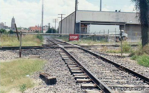 |
| A gate protecting an interlocking. Photo from forums at www.trains.com. |
No comments:
Post a Comment