Showing posts with label Couplers. Show all posts

Thursday, November 10, 2011

Tutorial: Cushioned Drawbars

Today I am sharing a video James and I made in July. James figured out a simple way to add working cushioned drawbars to model trains, and this video explains how. It is very easy to do, and adds that much realism to your freight cars. On the real trains, cushioned drawbars help to protect the load in the car by absorbing some of the impact during coupling, so the load doesn't move around as much. A lot of box cars and flat cars are equipped with these.

James and I hope to post videos more often, so be on the lookout for those! If you haven't already, you can subscribe to our YouTube channel and see videos there that we haven't posted here.

Anyways, my rant is over. Enjoy the video!

Wednesday, July 20, 2011

Prototype Railroading: Earning a Nickname

(Happy 100th Post!)

Railroading is one of those industries where sooner or later, everyone earns a nickname.  They never choose it.  It is chosen by other railroaders and eventually it just spreads.  It always starts because of a certain event.  As time goes on, people forget the story behind the nickname, but the nickname sticks.  If the stories can be remembered, they're usually pretty good, from a listener's point of view.  For the person who made the story, they can sometimes be embarrassing.  Fortunately, that is not always the case.

Yesterday, I earned my nickname.  People have started calling me "lucky."  For me, the story is not embarrassing.  Looking back, it is actually quite funny, although I was not having quite as much fun as I lived it!

In training, they try to go over as many different situations as possible so that when challenges arise later, as they inevitably will, and you do not have someone watching over and guiding you, you will be able to handle them as effectively as possible.  However, due to the nature of railroading and the length of the training program, it is completely impossible to gain experience in every possible scenario.  That takes an entire career.  As such, there are situations I heard about in training, and talked about, but never actually had a chance to work through and experience.  Yesterday I was able to check a few of those things off the list.

Yesterday, I was assigned to train H-PASGAL9-17A, a high priority merchandise train from Pasco, WA, to Galesburg, IL.  Merchandise trains carry just about anything, and have just about every type of railroad car in them.  Some cars are loaded, some are empty, and everything is mixed in everywhere.  Merchandise trains are well known for often having irregular handling characteristics and sometimes for having a bit of a mind of their own.  That being said, this was supposed to be a straightforward assignment.  The train had been rerouted, and since this was not the normal route, there were no cars to pick up or drop off anywhere along the way.  At the start, it looked like this train would be as easy as a coal train!

We got off to a slow start.  There were several groups of maintenance out working on the line.  We left Forsyth behind the most notoriously slow engineer in Glendive, which did not help the situation any.  We even dragged our feet leaving, so that we would not be too close behind him, but we still caught up to him within about twenty minutes.  It was the warmest day of the week, with highs predicted to be 102 degrees.  We would be moving slow, but at least we were sitting in an air conditioned cab.

About an hour into the trip, the air conditioner began blowing warm air.  This happens from time to time, especially when the locomotive is idle.  If the locomotive thinks it is idle, it turns off the air conditioner after a while to save energy.  Fixing it is easy, you just move the air conditioner switch to a different position and then back, and it lets the locomotive know you are still there.  That is exactly what we did, however, the warm air continued to flow.  We tried that a couple more times, with no additional success.  Finally, just to get air moving, we propped the front door open and opened the side windows.  That forces air through the cab.  While it was not any cooler, at least it was moving air, and it made the cab somewhat bearable.  At different stops along the trip, we tried different things to get the air conditioner working again, but we were unsuccessful, and the broom held the door open the rest of the way to Glendive.

Eight hours later, we were still on the move, and crossing the Powder River.  The dispatcher called us up on the radio to let us know that the mechanical department had spotted a hot journal bearing.  They told us what car it was on and which axle and we stopped as quickly as we could to look at it.  The journal bearing is at the end of the axle, and it is what supports the weight of the car.  The axle turns in the journal.  If they are working properly and lubricated properly, they only warm up a little.  However if there is a defect in the journal bearing, it can generate more friction, and therefore more heat.  If allowed to continue to operate, it can start fires along the railroad, and it can cause the metal to heat up enough to weaken it and cause the axle to break, resulting in a derailment.

Once we came to a stop, I grabbed my radio, infrared thermometer, and the work order, showing all the cars and their contents, and then I stepped off the train.  My engineer started to pull up, so I would not have to walk, but another problem presented itself.  He moved the train about three car lengths and then we heard a loud hiss, indicating that the emergency brakes had applied.  The engineer let me know the pressure at the rear of the train showed zero.  The air brake pipe had come apart somewhere.

At that point, I walked back to the car with the hot journal bearing.  I figured I would deal with that first, and then try to sort out why the train had gone into emergency.  Once I got to the indicated hot axle, I zapped it with the thermometer.  The journal was 168.8 degrees, which is warm, but not beyond the normal operating range, especially on a day as hot as it was.  I concluded that it was defect free.  When the indicated axle comes up okay, the policy is to check twelve axles ahead of and behind the indicated axle, just to make sure one of them did not set off the detector.  I did that, and found that they were all in the 150 to 170 degree range, so nothing was wrong there.  I figured the hot journal bearing was a fluke, and I began walking.  I still had to determine why the train had lost all air brake pressure and gone into emergency.

The train was 6,414 feet long, or about 1.25 miles.  That is a long walk, even in the shade, when it is 102 degrees outside!  Once the computer reset itself from the emergency brake application, the engineer placed the brake handle in release.  The brakes would only release if the pressure could build up to 90 pounds per square inch and then be maintained.  As the pressure started to build, the air flow meter indicated a leak.  It indicated that we were leaking about 100 pounds per minute, which is quite high.  That is a good indication that something came apart where it should not have.

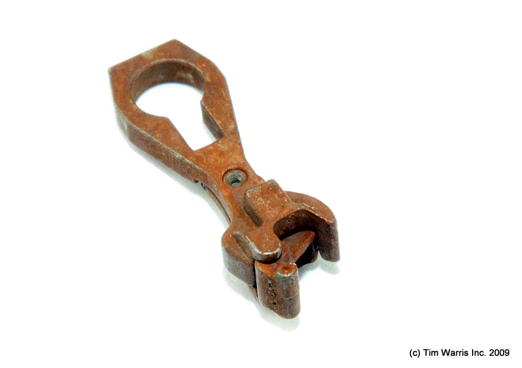
About 50 cars back, or half the length of the train, I heard a hissing.  Air was leaking.  As I got closer, I found that some air was leaking out where the hoses from two cars were coupled together.  I stopped for a minute to check it out, but determined that that was not the problem.  It was a small leak, and small leaks like that are actually quite common and really do not effect overall braking or handling.  I kept walking.  About 70 cars back, I began to hear another leak, but it was more of a wooshing noise.  It sounded like a much bigger leak. As I cam around the bend I noticed that there was about 75 feet between two cars in the train.  Something had come apart where it was not supposed to!  The 83rd car was the source of the wooshing noise.  The hoses, and cars had uncoupled.  When the cars uncoupled, the hoses came apart, letting all the air pressure out, causing the unexpected emergency brake application.  When I walked around the end of the 83rd car, I instantly saw the problem.  The coupler was missing its knuckle.  I had no idea where the knuckle was, although I could see exactly where it had broken off.

I let the engineer know what I had found, and then I closed the angle cock on the 83rd car, so he could start getting the air pressure back up on the front part of the train.  Then I got to work getting the remaining pieces of the knuckle off the car.  This was a little more difficult than removing a whole knuckle, because there was nothing left to grab.  Finally the biggest piece fell out, and the coupler was ready for a new knuckle.  The only problem was the new knuckle was on the locomotive, over a mile away.  About the last thing I wanted to do was walk that mile again, and then walk it a third time carrying a 75 pound hunk of steel!  Fortunately for me, the track inspector who had been following us overheard our predicament on the radio and offered his help.

The broken knuckle, after extracting it from the rest of the coupler.
Photo by James Ogden.
The track inspector drove to the locomotives, which were sitting by a highway, and picked up the knuckle and some water for me.  While he did that, I climbed up a hill to the nearest road, and met him in a pull out.  All I had to do then was hike back to the train with the new knuckle.  That was downhill, so gravity did part of the work.  Where the hill was steepest, I just tossed the knuckle down and let it roll.  I met it at the bottom.  Despite the walking saved by the track inspector, I was still completely exhausted by the time I got back the train!  Rather than walk aback the seven cars to the broken coupler, I asked the engineer to pull up.  By this time, it had been long enough that the air pressure had recovered in the front portion of the train, and he was able to move.  Once he moved the train, I installed the new knuckle, ensure that it was working properly, and then hopped on for the ride back to the rear portion of the train.  Once back there, we coupled the pieces of the train back together, made sure the coupler would hold, and then I coupled the air hoses again, so the entire train would have brakes.

Once all the work was done back there, it was time for the hike back to the head end of the train.  By then I was completely exhausted, and completely drenched in my own sweat.  I started hiking, and I immediately went for the second locomotive, because it had working air conditioning!  I sat in there for a few minutes and just enjoyed the nice, cool, refreshing air!  Once I had a couple minutes to cool off, I walked up to the lead locomotive, and we got underway again.  We finally arrived in Glendive nearly 12 hours after we had departed Forsyth.  It was a long day, but I guess it was one of those that turned into experience.

When we arrived at the yard in Glendive, we relayed the entire story to the crew van driver, and he was the one who decided that my nickname should be "lucky."  His reasoning was that typically knuckles break six to ten cars back, and I got one 83 cars back, on my first one, on the hottest day of the week, when the air conditioning was not working, and while trying to inspect a hot journal.  The really bizarre part is that the train was headed downhill.  Irony is what he was going for I guess.

Monday, July 18, 2011

Cushioned Drawbars

On the railroads, some freight cars have cushioned drawbars to help protect their load.  They absorb some of the shock of coupler slack running in and out.  They are most commonly found on cars which carry shiftable loads, such as centerbeam cars, bulkhead flat cars, vehicle carriers, and some box cars.  They can be added to model trains, although they require some minor modifications to the pocket that holds the coupler.  This project can be completed in just a few minutes though.

Original coupler pocket.  Photo by Steven Ogden.
Typically, inside the coupler pocket on most HO scale freight cars, there is a round peg that holds the coupler in position.  This allows it to swing from side to side, but usually it occupies most or all of the mounting hole in the coupler.  I use Sergent Engineering couplers on my cars, which have a round mounting hole, with a rectangular slot on the knuckle end of the hole.  By trimming the sides off the mounting pin, this will allow the coupler to slide in and out, while still allowing it to swing from side to side and holding it in the right place.  These modifications will work best with Sergent couplers, but they could be adapted for just about any type of coupler.

Modified mounting pin.  Photo by Steven Ogden.
To do this you will need a hobby knife or similar cutting tool.  You will also need a small spring for the cushioning effect.  If you are using Sergent couplers, you know they come with a small spring, and those work just fine.  For those of you who do not use Sergent Engineering couplers, the springs are available for sale on their website.  They should work just fine, regardless of what coupler type you are using.

Since the Sergent couplers already have a slot in them, in addition to the mounting hole, I cut the mounting pin down small enough to fit into that slot.  This will restrict side to side movement of the coupler when the drawbar is compressed, but on model trains, they serve very little useful purpose anyway!

Cushioned drawbar, with the coupler pocket still open.
Photo by Steven Ogden.
Once you have tripped the mounting pin to the appropriate size, it is time to put the coupler and spring in.  Inserting such a small spring can be a little tricky.  I find it is easiest to do with a small flat head screwdriver.  You can insert the screwdriver into one end of the spring, and then insert it at an angle.  Once it is in position, the screwdriver should come out without disturbing it significantly.  At that point, you will want to close up the coupler pocket before testing.  Testing it with the pocket still open could result in the tiny spring flying out and being lost forever!  Once you close it up, make sure to test it.  It will work best with the coupler centered.  If it works, put the car back together and enjoy!  If you notice that it is hanging up or is not working, you may have to open the coupler pocket again and make sure the modifications to the mounting pin are clean.  If there is any plastic that has not been removed properly, it could catch on the coupler and prevent it from working properly.  Chances are if the coupler does no work properly right away that is the problem.

Once the cushioned drawbars are complete, you will have protection from coupler slack for your model railroad loads.  However, because model railroad cars weigh so little, the cushioning will have very little effect on overall train handling.  In fact, unless your cushioned car is the first in a long train, you will hardly notice it!  If you put a couple of cushioned cars ahead of about 20 other cars, and then shove hard, you'll notice the drawbars absorbing some of the force, but they only work under extremes on the model railroad.

Monday, January 17, 2011

Prototype Information: Couplers

Once again, we visit the topic of couplers.  Some time ago, we talked about different options for model couplers.  Specifically, we talked about what is available HO gauge model trains.  Today, we are going to talk about what the prototypes, and how they are used.  I will warn you, this is a pretty technical post.

The modern knuckle coupler came to be in 1873.  Eli H. Janney is credited with the invention of the knuckle coupler, and his design is considered to be one of the most important advances in railroad technology, along with the Westinghouse Air Brake.  Both of those inventions completely changed how railroads operated, and made them significantly safer.

Photo from the Santa Cruz Lumber
Company Garden Railway.
www.santacruzlumberco.com
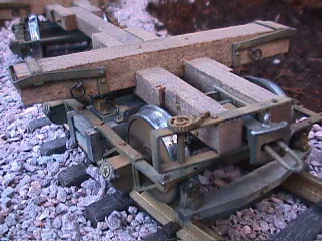
Before the invention of the modern knuckle coupler, railroads used a system of links and pins to connect railroad cars and locomotives.  The design was simple, but very dangerous.  It consisted of a socket on the ends of each car, and a link, similar to the link of a chain, being placed in the sockets.  Pins dropped through the sockets, and through an end of the link, to connect the cars.  A photo of this is on the right.  That link, sticking out of the socket, fits into a similar socket on another car.  A pin on each car secures everything in place.  There were three primary reasons this system was so dangerous.  First of all, it required the brakeman to stand between two cars as they were being coupled.  If they were coupled hard, that could mean the brakeman got run over.  Also, it meant that the brakeman had to align the pin with the opposing socket.  Again, a hard coupling could mean injury.  Many brakemen lost fingers and hands during coupling operations.  Many brakemen were killed just trying to couple cars.  The third problem was that there was often quite a lot of slack in a coupling.  This meant cars could move several inches, or even up to a foot without disturbing the other car.  When the train began to move, all the slack was pulled out, however, as a train slowed down, the slack all ran in.  If heavier cars were behind lighter cars, and all that slack ran into the lighter cars, it could mean a derailment.  Because of these safety problems, link and pin couplers are banned from interchange service in the U.S.  That is to say, they cannot be used on railroad cars that will leave home rails.

In April 1873, Eli Janney filed for a patent for his knuckle couplers. Since then, many variations have been produced, however the principle has remained the same.  The knuckle opens by pulling up on a link on the top of the coupler.  Often these links are connected to bars, allowing this operation to be done from the side of the train.  The link releases a pin inside the unit, which allows the knuckle to swing freely.  The knuckle is connected to a tongue inside the coupler.  As two couplers meet, the knuckles push on the opposing tongues, forcing the couplers closed.  Gravity drops the pin back in place, locking the couplers.  (See the animation below.)  Because of the automatic nature of the couplers, there is no need for a person to stand between cars or have their fingers near the couplers.  Despite the obvious safety reasons, this type of coupler was not required by law until 1893, and it was not standardized until 1916.  For those of you who learn better by seeing, take a look at the animation below.  It shows the basics of coupler operation.  The green parts represent the knuckle.  The white circle is where the pin drops to lock the couplers.  This would be a view looking down, at the top of the couplers.
Knuckle couplers in operation.  Animation from www.railway-technical.com.
Type E coupler.
 Photo from Wikipedia.
The most basic of the "Janney" coupler is called the type E.  The type E coupler, on the right, is also the most common.  This design can be found on almost any type of freight cars or locomotives anywhere in North America.  This specific variation of Janney's coupler was designed in 1932, and has been in widespread use since then.  Variations have developed since then for added safety, and for use in special circumstances.

The left coupler has a lower shelf.
 Photo from forum.atlassrr.com.
One of the variations designed for the type E coupler was to solve the problem of the coupler being able to uncouple if an extreme vertical force was placed on one or both coupled cars.  By the nature of the coupler, it is possible for couplers to slide up or down, and an extreme movement up or down would result in the couplers sliding apart, without the opening of the knuckles.  To solve this potential, although rare problem, shelves were added to the design.  There are two variations of shelves.  Some have just a lower shelf, as seen on the left, and others have a double shelf.  Lower shelf type E coupler can be found on just about any type of freight car.  They are typically found on cars that are less than about 30 years old, as the couplers came into use in the late 1970's.

Type E Double Shelf Coupler
Photo from www.model-railroad-hobbyist.com
The double shelf couplers have a shelf both above and below the knuckle, or coupling face of the coupler.  Again, this is to prevent couplers from sliding apart.  Double shelf couplers are required in the United States on all tank cars carrying hazardous materials.  This prevents couplers from coming apart in a derailment and puncturing the tank car.  The photo on the right is an example of a double shelf coupler.  This is a model, of such a coupler, but it accurately represents a modern type E double shelf coupler.

These type E couplers eliminated the biggest safety problems for brakemen.  It keeps them and their hands away from the couplers during operations.  It also keeps them out of the way of moving railroad equipment.  It partially solved the problem of the slack between cars, but did not eliminate it.  The slack was reduced enough to make it acceptable for freight trains, but it still allowed for some pretty uncomfortable jerking and bouncing in passenger operations.  Even in freight operations, it would be ideal to have no slack between cars.  Developments in couplers continued to try to eliminate slack from couplings.  The first of this development was the type F coupler.

Type F coupler
Image from www.mcconway.com
The type F coupler, seen on the left, was developed with shelves, and also with a type of tooth and socket.  The tooth and socket system was fitted to the sides of the design, and was supposed to help eliminate slack as much as possible between cars.  Versions were designed with just a lower shelf, and also with a double shelf, just as with the type E coupler.  The most common just has the lower shelf, as seen on the left.  The reasoning on the lower shelf here really had nothing to do with the couplers sliding apart.  The tooth and socket system prevents that.  However, these couplers are massive.  It was thought that if one was to break and fall into the track area, it could potentially derail the train behind it.  The lower shelf was built into the design to basically hold onto the opposing coupler, in the event of a break, and prevent it from falling into the tracks.  The type F coupler is found on a many modern locomotives.  It is also found on a lot of the rotary dump coal cars, because it prevents the cars from coming uncoupled while being dumped.

Type H coupler.
Photo by James Ogden
The type H coupler, on the right, is very similar to the type F coupler, and its main function is to eliminate slack between couplers.  This is known as a tightlock coupler, because there is no slack in the coupling.  Type H couplers have a similar appearance to the type F couplers.  They have the tooth and socket system on the sides, however, there are no shelves on a type H.  These couplers are found almost exclusively on passenger trains.  Occasionally they are found on locomotives dedicated to passenger service, although more often those use type F couplers.  There are two reasons these are used exclusively on passenger trains.  First, they eliminate coupler slack, which makes for a much more comfortable ride.  Secondly, in a derailment, a type H coupler generally stays coupled, eliminating the possibility of having the passenger cars jackknife.  In derailments where passenger cars jackknife, the number of serious injuries is typically significantly higher.  These couplers usually prevent that from happening.

Couplers have come a long way since the days of the link and pin.  They have also come a long was since Eli H. Janney first patented his new, safe, automatic knuckle coupler.  Safety has improved greatly, and continues to do so with the variations on Janney's coupler.  The basic design has remained the same since 1873, but the details have changed and standardized in the years since.  The type E, F, and H couplers are the industry standard today, and have proven to be reliable and safe.  When you are out railfanning, take a closer look at the couplers.  That is the best way to figure out what to put on your models.  You will start to see how different couplers are used, and see them in operation.

Wednesday, December 15, 2010

Couplers

(James)

When it comes to model railroad couplers, there are lots of choices.  There are many manufacturers, and many types within a manufacturer.  This gives modelers thousands of possibilities.  Overall, couplers can be broken into three basic types, which are horn-hook couplers, knuckle couplers, and scale couplers.

Horn-Hook Couplers:
Photo from www.amazon.com
Horn-hook couplers were standard for decades on model railroad equipment.  They did not operate prototypically, nor did they look anything like what one might find on an actual freight car.  If you wanted more accurate, knuckle couplers, they were aftermarket parts.  They could be purchased separately and installed.

Horn-hook couplers were used for so long because of patent requirements.  Kadee has been making knuckle couplers for a long time, but also owned all the patents on them for a long time.  As those expired, the horn-hook couplers began to disappear and other manufacturers began making knuckle couplers standard on their products.

Horn-hook couplers, though they were not much to look at, did have one major advantage.  They were, and still are, quite cheap.  To convert an entire fleet would not cost very much at all, although today it is difficult to even find anyone who makes horn-hook couplers!  Their biggest drawback had to do with reverse operations.  By their nature, they tended to put force in a sideways direction on the ends of the coupled cars.  As a train would move in reverse, this often resulted in the cars derailing on curves, picking switches, and going places you did not want them to go!  This problem was magnified as the train got longer.

Knuckle Couplers:
Photo from www.kadee.com
Knuckle couplers are basically the industry standard at this point.  Most of them have magnetic trip pins and can be operated automatically with a magnet or electromagnet under the tracks.  For many years, Kadee was the only manufacturer of knuckle couplers.  Recently, more companies have began making them, and now they are widely available.  They come in a few basic varieties.  They can either be metal or plastic.  They can be spring operated, in which there is a very small metal spring in place to ensure that the knuckle moves into places and couplers properly.  Others have a plastic tab to put pressure on the knuckle and move it into place.

The most reliable knuckle couplers are metal, spring operated knuckle couplers.  All couplers from Kadee are metal, spring operated couplers.  Now, there are a variety of particular types available, designed to represent prototype couplers.  You can find couplers which have shelves, such as those found on tank cars.  A more recent development is the plug and socket arrangement found on passenger cars and some locomotive couplers.  Various manufacturers make couplers that represent these features.

My personal preference, when it comes to knuckle couplers, is basically anything that is manufactured by Kadee.  All their couplers are metal, and generally they fit into just about any coupler mounting system without any modification.  The operate reliably for years, as long as the operating spring is not lost somehow.  They have magnetic trip pins, and can be operated remotely by a magnetic device beneath the tracks.  Other manufacturers include McHenry, Proto, Atlas, Kato, and Athearn, to name a few.  They are all compatible with different brands, however, they are not compatible with any other type of couplers.

Knuckle couplers have several advantages.  They look considerably more realistic than horn-hook couplers.  They operate much better, and there are no problems when backing.  They do tend to be a bit more expensive than horn-hook couplers, depending on which brand you buy.  I think it is worth the extra cost for the added realism and better operation though.  I would much rather spend the extra money on knuckle couplers rather than horn-hook couplers!

Scale Couplers:
Photo from www.bronx-terminal.com
My favorite couplers are scale sized knuckle couplers.  These look the most realistic simply because they are exact models of the real thing, scaled down to 1/87 of the original size!  So far, I have only found one manufacturer, and that is Sergent Engineering.  There are several types available, and they are exact replicas of the various prototype coupler types.  These operate a bit differently than either the horn-hook or typical knuckle couplers talked about earlier.  They do not depend on spring pressure to keep them engaged.  These couplers are engaged when another coupler mates with them.  Inside, there is a ball bearing which acts as a locking mechanism.  When the coupler is closed, the ball bearing falls into place, much like a pin on the prototype, and locks the coupler closed.  The coupler is unlocked by lifting the ball bearing with a magnetic wand.  There is no spring or plastic tab to wear out, and therefore less chance that the coupler will stop engaging properly after time.

These couplers have never come standard on equipment.  They have only been manufactured in fairly small quantities, usually depending on the number of orders.  Typically, if you want these on your equipment, they will have to be installed as aftermarket parts.  This leads to one major drawback.  These couplers are expensive!  Depending on what type of couplers you are looking for, they can be as little as $1.72 for a coupler, or as high as $3.25 per coupler!  I have lately been using parts from two different coupler types to make passenger car couplers, and when you do it that way, the price goes up to at least $4.97 per coupler!  If you are thinking about converting an entire fleet, you may have to plan on doing it in phases.  This is also a bit of a problem though, because these couplers are not compatible with any others.  If you convert in phases, some of your equipment will not be able to be coupled to other equipment.

Operationally, these couplers are outstanding.  When new, they do need to be broken in.  This is a fairly simple process which involves applying a little graphite to the moving parts of the coupler, and then opening and closing it repeatedly until everything is pretty well coated in  the stuff.  If that is done properly, these couplers will operate without any problems for a long time.  They operate realistically, in that something needs to unlock them before they will open.  I have never had a problem with them uncoupling during operations.  These couplers are all metal, and are quite strong.  These couplers do not center themselves, the way most standard knuckle couplers do, which does make coupling on curves and switches easier.  It also means that the operator has to make sure couplers are aligned to receive when coupling.  Failure to do this means that a coupling will not likely be made.

At this time, remote uncoupling is not available from Sergent Engineering.  This means a model railroad would need to be designed with the tracks within reach to facilitate uncoupling.  I have read in a few places about people installing electromagnets under the tracks to enable remote uncoupling.  The idea is that the electromagnet, when activated, could repel the ball bearings inside the couplers, pushing them up, and allowing the coupler to open.  While I have not personally tried this, I have heard of it working for some people.

These couplers have some very good advantages.  They look great, and the operate flawlessly.  They do add a new level of realism to operations.  They are durable, and because of their size, there is extremely little slack action in a whole train.  Their biggest disadvantage is the price.  Since they are so expensive, it is unlikely that anyone would convert the entire fleet at one time, and then you run into the problem of them not being compatible with any other couplers.  I have chosen to use these on my model trains.  I started with about the half the fleet, and then converted the other half.  At this point, I try to keep a few on hand for whenever I acquire new equipment.  Before new equipment hits the rails, it gets a new set of couplers.

Couplers are one of the smallest, yet most important parts of operations.  Choosing the right couplers is very important.  The sooner a choice is made to standardize, the easier the conversion is.  This ought to give you an idea of what is out there, and what you may want to use.  As always, let us know if you have questions or if you would like more information.  We would love to help if we can!